Collaboration
From Business Process Management, BPM and Workflow Automation Wiki | BizAgi BPMS
<keywords content="keywords">collaboration diagram, collaboration diagrams, diagram, diagrams, collaboration, create, remove, edit, move, collaboration, communicate processes, IsThrow, Is Throw, message, throw, catch</keywords>
Contents |
Collaboration
Processes can communicate between each other through message flows. This type of communication is called Collaboration. Collaboration is a Tool that relates two or more processes allowing them to communicate with each other by sending and receiving messages containing information to take actions.
In Bizagi, collaboration is done through the throw and catch shapes which are configured in each process. The shapes that allow Collaboration in Bizagi are:
Message Start: With this shape, An active process sends a message to another specific Process in order to trigger its start. Message Start is always a catch shape. In order to find more information about this shape, please follow the link.
![]()
![]() Message Intermediate Event: This shape has a throw and a catch option, which is to send a Message or receive a Message (When used to throw the message, the shape is filled. When used to catch the message, the shape is unfilled). More information is available In this article.
Message Intermediate Event: This shape has a throw and a catch option, which is to send a Message or receive a Message (When used to throw the message, the shape is filled. When used to catch the message, the shape is unfilled). More information is available In this article.
Message End: This type of End indicates that a Message is sent to a specific process or active case, at the conclusion of the Process. Message End is always a throw shape. In order to find more information about this shape, please follow the link
Signal Start: With this shape, an active process sends a Signal and triggers the start of another Process. Signal Start is always a catch shape. In order to find more information about this shape, please follow the link.
![]()
![]() Signal Intermediate Event: Signals are used for sending or receiving general communication within and across Processes. A BPMN Signal is similar to a signal flare that shot into the sky for anyone who might be interested to notice and then react. Thus, there is a source of the Signal, but no specific intended target. This shape has a throw and a catch option, which is to send a Signal or receive a Signal. When used to throw the signal, the shape is filled. When used to catch the signal, the shape is unfilled. More information is available In this article.
Signal Intermediate Event: Signals are used for sending or receiving general communication within and across Processes. A BPMN Signal is similar to a signal flare that shot into the sky for anyone who might be interested to notice and then react. Thus, there is a source of the Signal, but no specific intended target. This shape has a throw and a catch option, which is to send a Signal or receive a Signal. When used to throw the signal, the shape is filled. When used to catch the signal, the shape is unfilled. More information is available In this article.
Signal End: This type of End indicates that a Signal will be broadcasted when the End has been reached. Signal End is always a throw shape. In order to find more information about this shape, please follow the link.
How to Configure Collaboration
In order to convert an intermediate event into a throw message there are two steps:
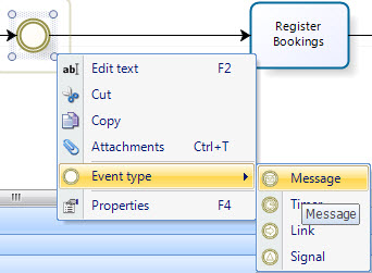
1. Convert the Event Type from intermediate Event into Message by doing right click, and then Event Type -> Message
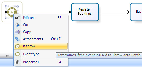
2. Once the Intermediate Event is converted into Message, right click and select IsThrow in order to convert the message into a throw message.
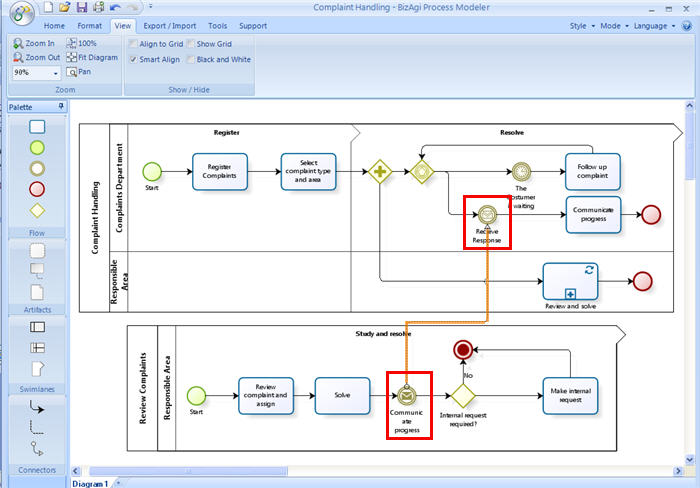
In the collaboration diagram, the messages will appear as follows:
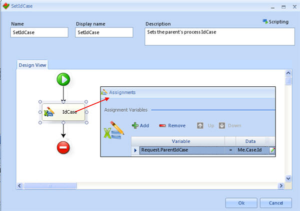
In order to configure Collaboration through Messages, it is necesary to relate an Expression that sets the IdCase to an attribute in the data model. This has to be done in the process that Catches the message. If the catch Event is a Message Start, there is no need to perform this step, since the idcase is still unknown for the case that would be created.
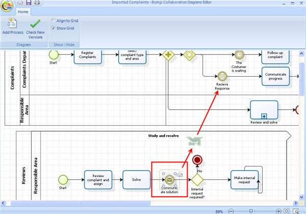
Once the Message Events (throw and catch) are created, a message can be created when two or more process are imported, following these steps:
1. Import or create the collaboration diagram.
2. Click on the THROW message shape. When this is done, a small envelope appears in the upper right-hand corner of the shape.
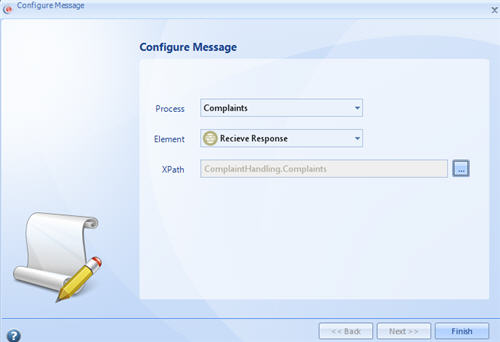
Drag the envelope to the CATCH shape and configure the message.
Note: If the throw message already has a message configured, the small envelope will not be shown.
Important: When the shape to throw a message is being configured, it is necessary to specify the process, the shape and exactly what case will receive it (i.e. the id case of the process that has the catch message event). The case number that will receive the message must be stored in the data model since the xpath of this idcase is one of the parameters of the message that is created. Please keep in mind that when the catch message event is a Message Start shape, the xpath field where the idcase is mapped is not editable, since the case in the process b is going to be created. In the next example the case number is already saved:
Watch the video to learn how the operation of sending and receiving messages works, and how to configure the messages using the process wizard.
<videoflash>w-bEnf7AtqA|640|505|</videoflash>
Example
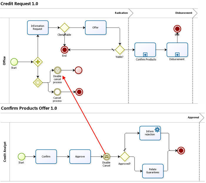
In a Credit Request process, as soon as a request is created, two paths are enabled.
The first path is the normal process, which obtains information from the client in order to evaluate the products requested.
The second path is a Case Cancellation option. This path should be available until the case has been examined by the Credit Analyst. As soon as it is approved or rejected, the Cancellation option must be disabled.
In order to do this, the Credit Request process has a Message Intermediate Event that will catch the message of the Confirm Products process, as soon as the request is examined by the Analyst.
Collaboration Diagrams
Collaboration Diagrams are the elements that allow the user to view, create and configure the interaction between processes.
|
Warning: Diagrams are only a VIEW of how the collaboration between processes works, they are not the actual processes. If a diagram is removed it will not erase the processes. |
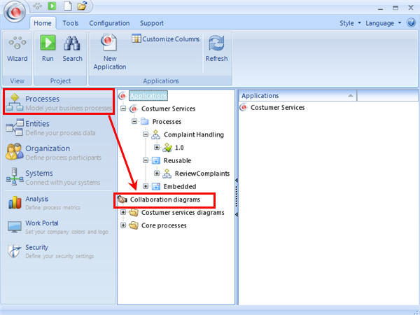
Collaboration Diagrams are available in the Modules View, via Processes in the Main Menu.
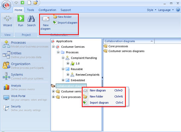
Diagrams can be created, imported and arranged into folders.
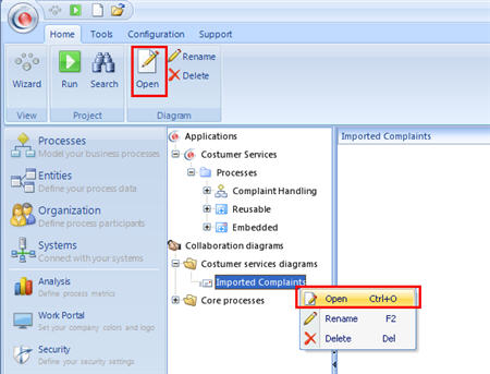
The functionality that can be accessed by right clicking over the menus can also be accessed through the toolbar on the top of the screen.
Import the diagram when the processes are created in Bizagi's Process Modeler, and you want to automate them. When a diagram is imported, the processes contained will be created as actual processes in the Applications node.
Create and Edit the diagram when the processes are already created and you just need to see the collaboration between them.
Folders help the user arrange the diagrams in a hierarchical manner. They can be created at any time even within an existing folder. To create a folder, right click over the Collaboration Diagram menu or over an existing folder, according to the hierarchy desired. Select New Folder. Diagrams can be dragged and dropped into folders at any time.
Import a Collaboration Diagram
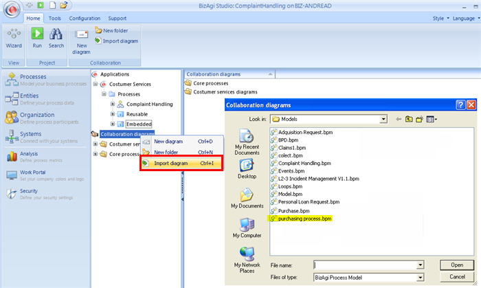
To import an existing diagram, right click on the Collaboration diagram menu, or on a folder, and select Import Diagram.
1. Select the file created in the Bizagi Process Modeler (.bpm file). Files must have at least one process. If the file is blank, an error message will be displayed.
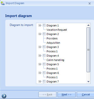
2. A new window will show the available processes. Select the process and click on Next.
Name the Diagram and the Process. Then click on Finish.
The diagram will be imported as well as the Processes within it. The process will now be available to automate in the Application node.
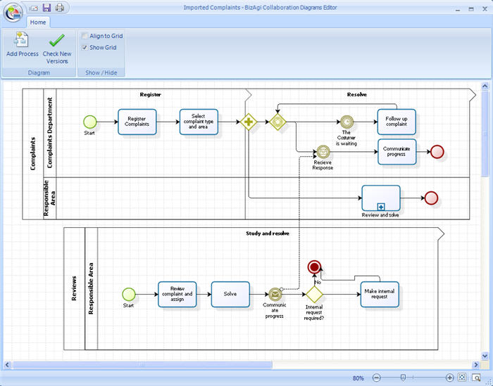
The BPM model that looks like the first image below, will be imported and displayed like the second image:
Create a Collaboration Diagram
Diagrams can be created using the existing processes in the project.
- To create a blank diagram in which to add a process, right click on the Collaboration Diagram menu, or on a folder, and select New Diagram.
Edit a Collaboration Diagram
- To rename a diagram, right click over the diagram and select Rename. Type the desired name.
- Also, diagrams can be moved from one folder to another.
- To edit the contents of the diagram, right click over it and select Open.
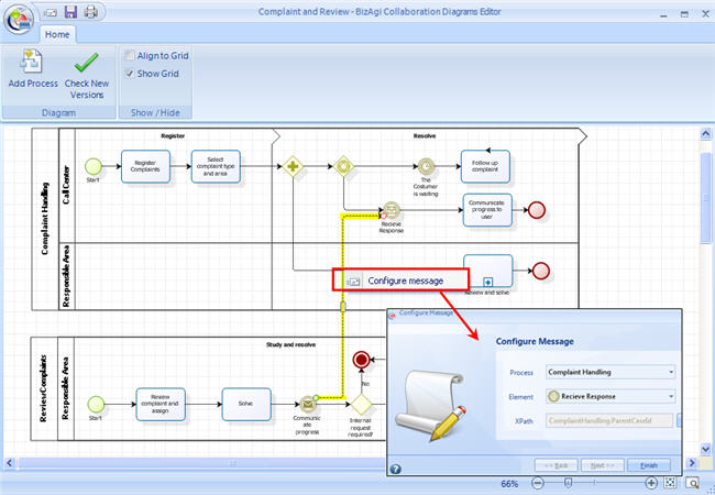
The Diagram is presented as a drawing area (Diagrams Editor) in which the processes are shown, including the messages that are exchanged between them. Messages are represented with dotted lines, as shown in the image above.
When the Collaboration Diagrams Editor is opened the user can:
- Add processes
- Remove processes
- Move processes (change their location in the diagram)
- Create messages between two processes
- Configure an existing message
- Collapse and expand processes.
Add a process
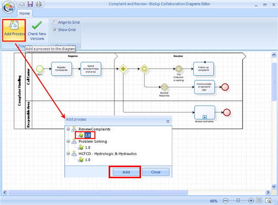
To add a process to the diagram click on the Add Process button on the top of the screen.
A new window will display the available processes. Click on the desired Version of the process and then Add.
Remove a process
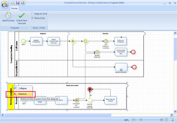
To remove a process from the diagram, right click over the name of the process. Select Remove.
Move a process
To move a process on the diagram, click over the name of the process. Move it to wherever desired.
Collapse and Expand
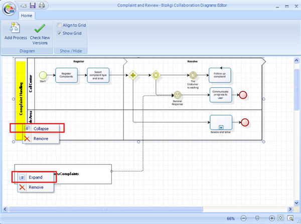
Processes can be collapsed and expanded as shown in the image.
Click on the name of the process and select Collapse or Expand.
Delete a Collaboration Diagram
To delete a diagram, right click over it and select Delete. The process WILL NOT BE ERASED.
Configure an existing message
Messages should be configured in order to send and receive them correctly.
Right click over the dotted line and select Configure Message.
Verify Process Version
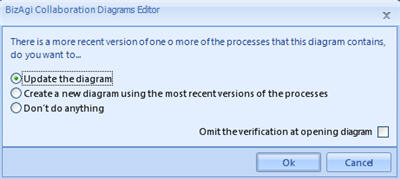
A message will appear when the diagram is opened and a new version of a process is available. These are the available options:
- Update diagram
- Create new diagram with updated processes
- Do nothing and open the saved diagram.
On the top of the screen there is an option to Check for New Versions at any time.
Related Information
- To use collaboration from the Modules view: Message Intermediate Events and Message Start
<comments />
