Modeler
From Business Process Management, BPM and Workflow Automation Wiki | BizAgi BPMS
<keywords content="keywords"> model, modeling, stencil, palette, shape, task, activity, model, modeling, diagrams, drawing, Process Modeler, Bizagi Process Modeler, model the process, processes, diagram, document, documentation </keywords>
Contents |
Bizagi Process Modeler
Bizagi Process Modeler allows users to diagram, document and share their business processes in a standardized way. The Modeler uses the BPMN (Business Process Management Notation), a worldwide standard that enables the design of simple and complex processes for multidisciplinary teams.
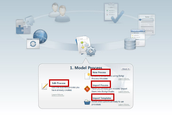
The first step is to diagram the process. Once it is diagrammed, users can export it to several files: pdf, Word, Visio and XPDL. Users can also share the processes in the Web, Sharepoint and Wiki. To access the process modeler select the first step in the Project Wizard and click on Edit if a diagram has already been created, New to create a new diagram, Import to import a bpm diagram or Import template to enter the Process Central and download a ready-to-use template.
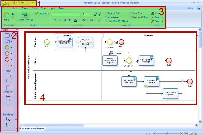
On the main screen of the modeler, there are different menus to access the tool’s functionalities. The main screen is divided into four sections:
|
1.Main Menu: This option enables you to Export, Import, Save, Print and Publish the diagram. 2.Shapes: This bar contains the different shapes to model the process. 3.Bizagi Process Modeler Menu: This menu contains the options of Home, Format, View, Export/Import and Tools 4.Work Area: the area where the process diagram is modeled. |
Choose the desired shapes
To model the Process just drag and drop the desired shape from the Palette. This bar contains the BPMN shapes to create the desired process flowcharts, simple or complex.
1. In the Bizagi Process Wizard select the desired process to Create or Edit a process
2. To use any of the BPMN shapes on the drawing Palette, select it, drag it and leave it on the point in the diagram it should be placed.
3. Should you need one of the shapes that is not shown on the drawing palette but is part of the menu, use the arrow to display them and use the shape you need.
In the top right corner there is an option called Mode. This option allows the user to hide or show the shapes. Core will enable only the basic shapes. Extended will enable all shapes.
|
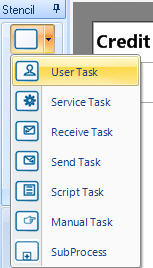
Example: Select the task you would like to use: user task, service task or Sub-process. |
|
Note: Each shape has a description. To view it, place the cursor over it. |
|
Note:To create a lane or a Phase, refer to How to Create a Phase or How to Create a Lane. |
Diagram the Process
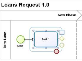
Shapes have a circular menu, which enable to select the shapes and connect them. When the cursor is placed over them a translucent frame is drawn in the same color as the shape. Click on the shape and the icons of the shapes that are available to be connected will appear. These icons enable to drag and drop the shape they represent. When you selected, a new shape is created along with the sequence flow that leads to it.
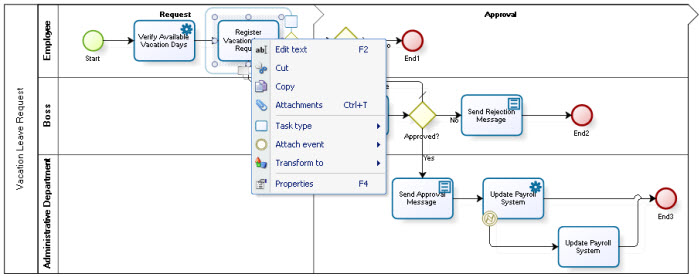
Each shape in the diagram can be edited to change its type, text, to transform it and more. According to the shape, different options will be displayed.
Right click over the shape to display all the options.
- Edit Text: enables the text of the shape to be changed.
- Attachments: each shape can contain attachments that will be displayed when viewing the process in Presentation Mode or in any of the exported file types.
![]() User tasks, gateways and events have the functionality to transform into another shape from the same category. For instance, you can transform a user task into a service task or a Sub-process.
User tasks, gateways and events have the functionality to transform into another shape from the same category. For instance, you can transform a user task into a service task or a Sub-process.
- Shape type: Change the shape type from within the family types.
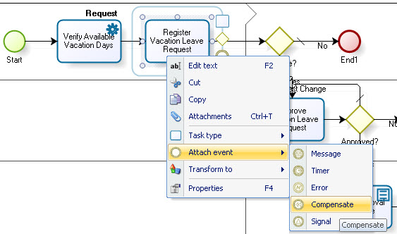
- Attach event: attach any type of Event type shapes to Task shapes.
- Transform: To make the transformation, select the shape and right click on it. In the menu displayed, select the Transform option and then select the shape to change it to. The shape is transformed automatically.
- Associate an Event: Events such as Compensation Events, Cancellation Events, Timers and Messages can be associated to activities. Select the shape, right click on it and click on Attach. Choose the event desired.
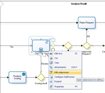
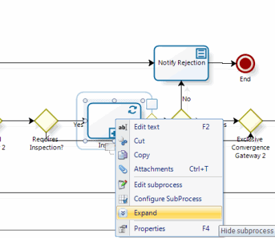
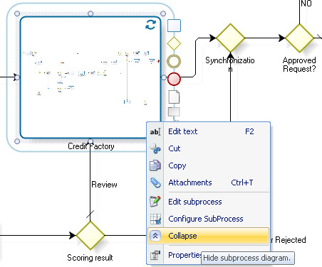
![]() Suprocess can be edited, configured and expanded as necessary.
Suprocess can be edited, configured and expanded as necessary.
- Edit Subprocess: Opens a subprocess to be edited on a new window
- Configure Subprocess: Opens the Subprocess Wizard to configure its properties
- Expand: Displays all the Subprocess shapes that are contained showing them in the parent process.
- Collapse: Collapses an expanded subprocess to a single task shape.
![]() Gateways can be transformed to a shape of the same family. To make the transformation, select the shape and right click on it. In the menu displayed, select the Transform option and then select the shape to change it to. The shape is transformed automatically.
Gateways can be transformed to a shape of the same family. To make the transformation, select the shape and right click on it. In the menu displayed, select the Transform option and then select the shape to change it to. The shape is transformed automatically.
How to delete a Shape in the Diagram
1. Select the shape and press the delete key. You can select several shapes at the same time.
|
Note An element that is connected to other elements can be deleted. However when the shape is deleted any related information is also eliminated. |
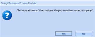
Click on the “OK” button of the confirmation window. When several shapes are deleted at the same time, just one confirmation message is displayed.
|
Note To delete a functional area or a phase, refer to How to Delete a Lane or How to Delete a Phase. |
Process and Shape’s Properties
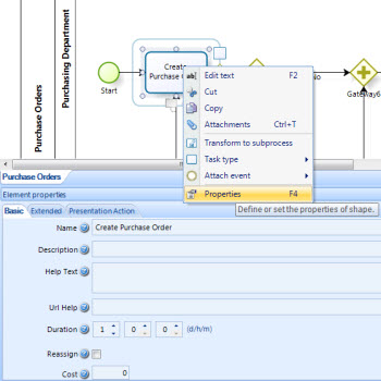
The Process and every shape contained in the diagram have specific properties divided into three tabs: Basic, Extended and Presentation Actions. The fields displayed in every tab vary between shape types. Right click on the Process Name or on any shape and select Properties to access this properties.
Basic Properties include the Name and the Help Text of tasks are shown in the web application when the each activity is enabled.
For documentation purposes the tabs Extended and Presentation Actions will be used to displayed information when the process is Exported or viewed in Presentation Mode.
For further information please go to Shape Properties
Share Processes
Every process diagrammed in Bizagi Process Modeler can be shared with your team in many different ways. Diagrams can be opened in Presentation Mode; they can be Exported to images, Word, PDF, Visio and XPDL files. They can also be Published to SharePoint, the Web and Wiki.
Click to learn more on How to Import, Export and Share processes.
Bizagi Process Modeler Button
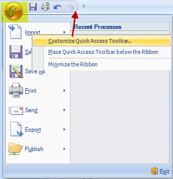
The Bizagi Process Modeler Button contains a Quick Access Toolbar and a list of items used to work with the Modeler file.
The Quick Access Toolbar is a customizable tool that contains a set of separate commands. The bar makes it easier to access frequently used options with just one click. By default, the modeler four five options available: Save, Print, Undo and Redo.
By clicking in the Modeler Icon on the upper left corner, the user can access several additional items: Export, Import, Save, Print and Publish. These items can be added to the Quick Access by right clicking on them and selecting Customize Quick Access Toolbar. This will display a new window where all the menus are displayed to be added.
Save and Save As
Save function allows the user to save the process in the database. This includes not only the shapes that are drawn, but also their positions, which will be illustrated in the flow presentation, with the graphic consultation option.
Save As function allows the user to save the process as a BPM file. That is, a file to be opened and consulted in the Bizagi Process Modeler.
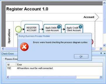
If the diagram contains any errors, a window is displayed at the bottom of the work area with a list of errors in the process, indicating the shape and a description of the error. In addition, a window is displayed informing that errors were found when verifying the syntax of the process diagram and that the elements were not saved.
Click on Accept in the confirmation window to access each entry on the list. Double click on an entry to go to the shape where the error was found and it will be pointed out in the diagram.
|
Note: it is essential to constantly validate the diagram and save the flow in the database every time any changes are made. |
This option is used to print the diagram. In order to do so, a new window will ask the user to select the printer. Click OK to print. <comments />
